Skip to content
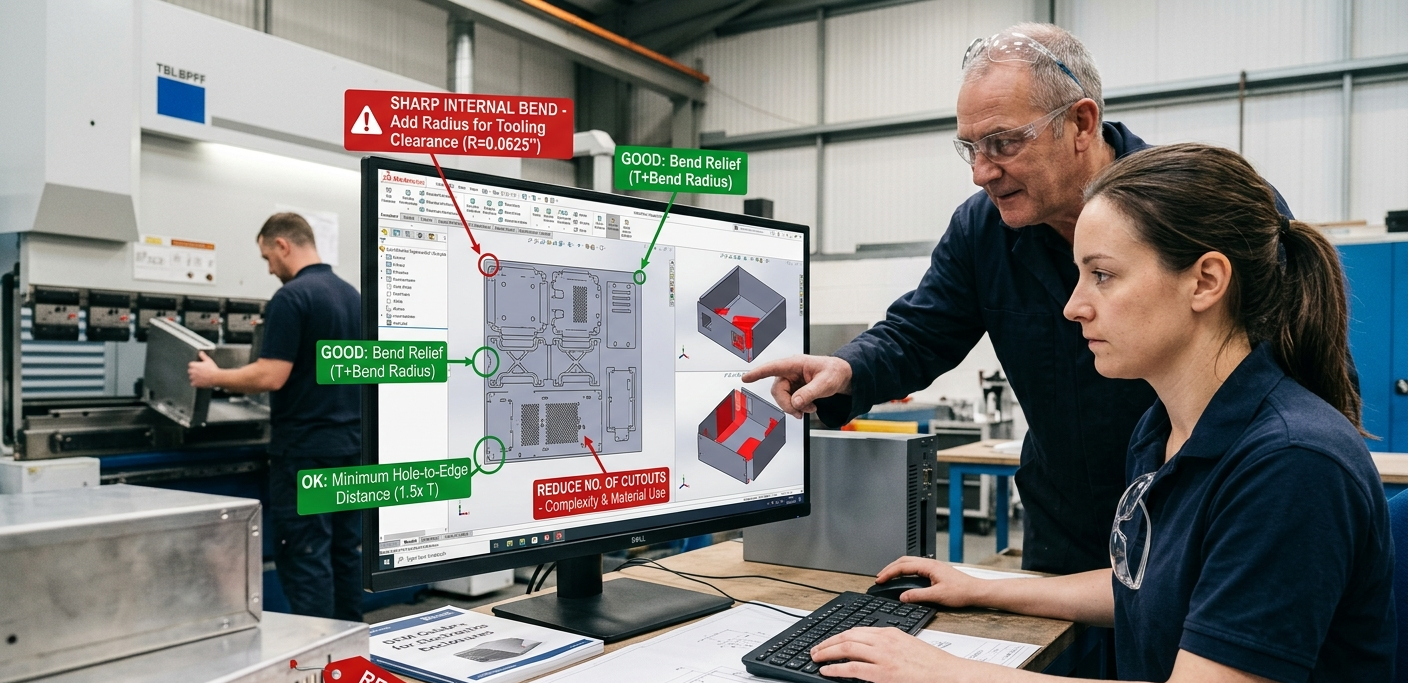
Sheet metal DFM (Design for Manufacturing) is the practice of reviewing a design before fabrication to identify features that drive up cost, slow down production, or increase scrap rate. Applying these 12 rules before releasing a design to quote typically reduces fabrication cost by 15–40% and eliminates the most common causes of rework and delayed delivery.
12 Sheet Metal DFM Rules: Quick Reference
The table below summarises all twelve rules with the production problem they prevent and the specific guideline to follow.
| DFM Rule | Why It Matters | The Guideline |
|---|---|---|
| Minimum Bend Radius | Too-tight radius cracks material; increases springback and scrap rate | Minimum inside radius = 1x material thickness for steel; 1.5x for aluminum |
| Hole-to-Edge Distance | Holes too close to edges deform and elongate when bent | Minimum distance = 2x material thickness from hole centre to edge |
| Hole-to-Bend Distance | Distortion of hole geometry when bent too close to a feature | Minimum distance = 2.5x material thickness from hole edge to bend line |
| Minimum Hole Diameter | Small holes are slow to punch and prone to tool breakage | Minimum hole diameter = 1x material thickness (laser allows smaller) |
| Bend Relief | Relief notches prevent tearing at intersecting bend lines | Add relief cutout of 1x thickness wide × 1x thickness deep at corners |
| Consistent Bend Radii | Multiple radii require multiple tooling setups, adding cost | Standardise all bends to one radius if possible; 2 max per part |
| Hem Geometry | Hems strengthen edges but must be sized to fold reliably | Open hem gap ≥ 4x material thickness; closed hem minimum 0.5 mm |
| Tab and Slot Alignment | Misaligned tabs and slots create weld distortion and rework | Tab width = slot width + 0.1 mm; slot depth 80–100% of tab length |
| Countersink Depth | Overly deep countersinks weaken sheet; too shallow lets fastener protrude | Countersink depth ≤ 2/3 of sheet thickness for t < 3mm |
| Stamped Feature Depth | Deep formed features require progressive tooling, increasing cost | Emboss depth ≤ 3x thickness; lance height ≤ 2x thickness |
| Grain Direction | Bending across grain increases springback and cracking risk | Orient critical bends perpendicular to material grain direction |
| Weld Joint Access | Poor access forces difficult out-of-position welds, reducing quality | Allow minimum 20 mm clearance on each side of all weld seams |
Why DFM for Sheet Metal Is Different from Machining DFM
The Sheet metal fabrication involves a fundamentally different set of physical constraints than CNC machining. In machining, material is removed from a solid billet by cutting — the designer has nearly unlimited freedom in feature geometry as long as the tool can reach the feature. In sheet metal, the material is bent, cut, punched, and formed along its thickness dimension, and the physics of plastic deformation in thin metal sheet impose constraints that designers must understand and respect.
The most important of these constraints is springback: after a press brake bends the sheet to a target angle, the material elastically recovers a small amount when the punch retracts, resulting in an angle that is slightly more open than the tooling angle. Springback magnitude depends on material type, temper, thickness, bend radius, and grain direction. Managing springback requires over-bending to compensate, which is standard practice but must be dialed in for each material and geometry. DFM designs that use consistent material specifications, consistent bend radii, and grain-direction-compliant bends are far easier to control than designs that mix materials, radii, and bend orientations.
Another key sheet metal constraint is the minimum material needed between features. In machined parts, you can cut a pocket right up to the edge of a workpiece as long as the tool fits. In sheet metal, cutting a hole too close to an edge or too close to a bend line causes the material in the thin web between the features to deform, elongate, or tear during forming. The hole becomes distorted and no longer meets its positional or dimensional specification. DFM rules around minimum distances between holes, between holes and edges, and between holes and bend lines are not arbitrary conservatism — they reflect the physics of thin sheet metal forming.
- Sheet metal DFM constraints come from: springback physics, minimum web thickness between features, punch breakage limits on small holes, tooling clearance requirements for hem and offset operations
- Unlike machining DFM (which is mainly about tool access), sheet metal DFM is primarily about forming physics and tooling compatibility
- A DFM review before quoting typically takes 2–4 hours for a complex part and saves days of rework and redesign after first article inspection
Rule 1–2: Bend Radius and Material Thickness
The most fundamental sheet metal DFM rule is minimum bend radius. When a sheet is bent, the outer surface of the bend is placed in tension and the inner surface in compression. If the bend radius is too tight relative to material thickness, the tensile stress on the outer surface exceeds the material’s elongation limit and cracking occurs. The minimum safe inside bend radius for common sheet metals is: mild steel (CRS 1008/1018): 1x material thickness. Stainless steel 304: 1x–1.5x thickness. Aluminum 5052-H32: 1.5x thickness. Aluminum 6061-T6: 2x–3x thickness (due to lower elongation). Copper and brass: 0.5x–1x thickness.
Designing below these minimums is not just a quality risk — it is a lead time risk. When a first-article part cracks at a tight bend radius, the engineering team must redesign the radius, update the drawing, re-release the file, and re-quote. This process adds one to three weeks to the program timeline. Catching the radius issue during DFM review takes five minutes and costs nothing.
Xinyang Industrial Tech’s DFM review automatically flags any bend radius below the material-specific minimum for the requested material. When you upload a file at xinyangmfg.com, the engineering team checks every bend against material specifications before the quote is issued.
Rule 3–4: Hole Placement Relative to Edges and Bends
Holes in sheet metal must maintain minimum distances from edges and from bend lines. The edge distance rule: hole centres must be at least 2x material thickness from the nearest cut edge. Closer than this, the thin web of material between the hole and the edge deforms when the punch enters, creating an elongated or teardrop-shaped hole. The bend distance rule: hole edges must be at least 2.5x material thickness from the nearest bend line. Holes closer than this stretch and distort during bending.
A common design mistake is placing mounting holes at the very corner of a bracket, where the hole is close to both the edge of the flange and the bend. This compound proximity — near both the edge and the bend — creates the worst-case forming condition and almost always results in a distorted hole after bending. The fix is simple: move the hole inward on the face, away from the edge, and maintain the 2.5x clearance from the bend line. On small brackets where this creates a conflict with the required bolt pattern, consider whether the bent flange height can be increased to give more clearance.
- Hole-to-edge minimum: 2x material thickness from hole centre to nearest cut edge
- Hole-to-bend minimum: 2.5x material thickness from hole edge to nearest bend line
- For Ø5mm hole in 2mm steel: minimum 4mm from edge; minimum 5mm from bend line
- Workaround for tight constraints: use weld nuts instead of punched holes near bends
Rule 5–6: Bend Relief and Consistent Bend Radii
When two bend lines intersect — such as at the corner of a formed box — the material must be relieved to prevent tearing. Without a bend relief notch, the material at the intersection is pulled in two directions simultaneously during bending, causing it to tear unpredictably. Bend relief notches are small rectangular cutouts placed at the intersection of two bend lines. The required geometry is: notch width ≥ 1x material thickness; notch depth ≥ 1x material thickness into the corner. Adding bend relief costs nothing in laser cutting time (the notch adds a fraction of a second to cut) and prevents a failure mode that is expensive to rework.
Consistent bend radii across a part dramatically reduce press brake setup time and cost. Every change in bend radius requires the operator to change the press brake punch and die toolset, which takes 5–20 minutes. A part with three different bend radii requires three tooling setups and three sets of operator quality checks before the first piece is formed. A part with one consistent bend radius requires one setup. For complex brackets with eight or ten bends, standardising all bends to a single radius (typically 1x or 1.5x material thickness) can reduce press brake time by 40–60% and lower part cost proportionally.
Rule 7–8: Hem Geometry and Tab-and-Slot Alignment
Hems are folded edges that strengthen sheet metal parts, eliminate sharp cut edges, and create a finished appearance for exposed surfaces. A hem is formed by bending the sheet back on itself 180 degrees, creating a double-thickness edge. Open hems (with a small gap between the two layers) are easier to form and more forgiving than closed hems (where the layers are pressed flat together). The DFM rule: open hem gap must be at least 4x material thickness to allow the forming punch to engage correctly; closed hems require the base material to extend at least 3x the hem width from the bend line.
Tab-and-slot joints are a common sheet metal assembly technique that aligns mating parts during welding and eliminates the need for external fixturing in some cases. For tab-and-slot joints to function correctly, the tab width must be 0.1 mm larger than the slot width (for a slip fit), the slot depth should be 80–100% of the tab length, and both tab and slot must account for laser kerf width in their nominal dimensions. A common error is designing tabs and slots at identical nominal dimensions — this results in an interference fit after laser cutting due to the kerf, requiring force assembly that damages the part geometry.
Rule 9–12: Countersinks, Stamped Features, Grain Direction, and Weld Access
Countersunk holes in thin sheet metal are a particular challenge. The countersink must not penetrate more than 2/3 of the sheet thickness, or the remaining wall is too thin to resist the clamp load from the fastener. For sheet thinner than 3mm, specifying a countersunk flathead fastener is often a design mistake — a pan head or button head fastener with a counterbore in a thicker boss insert is a better solution. When a countersink is truly required in thin sheet, consider a PEM hardware insert (pressed-in hardware) instead of a machined countersink.
Stamped features including embosses, louvers, and lances add stiffness, ventilation, or mounting features to sheet metal parts. The DFM limits: emboss depth maximum 3x material thickness; lance height maximum 2x thickness. Exceeding these limits requires progressive tooling and multiple forming passes, which add significant cost. Grain direction — the direction of the metal rolling process visible as a subtle texture direction on mill-finish sheet — affects formability significantly. Critical bends should be oriented perpendicular to the grain direction (bending across the grain) to minimise springback and cracking risk. Bending parallel to grain increases cracking risk by 30–60% on high-strength alloys.
Weld access is the final and often overlooked DFM rule. Welds require physical access for the welding torch, the filler wire, and the operator’s line of sight. A minimum of 20 mm clearance on each side of every weld seam is the standard guideline. Enclosed boxes and channels with weld joints at the bottom of deep flanges are among the most common DFM failures submitted to Xinyang. When weld access cannot be achieved with the designed geometry, alternatives include: expanding the part opening, replacing a continuous weld with spot welds or plug welds through drilled access holes, switching to a press-fit mechanical joint, or splitting the part into two sub-assemblies that can be welded in open access before assembly. Upload your design to xinyangmfg.com for a free DFM review that covers all twelve of these rules.
DFM Review Workflow at Xinyang Industrial Tech
When a design file is uploaded to Xinyang’s quoting platform, the engineering team runs a systematic DFM review covering all twelve rules in this guide plus additional checks for hardware insertion compatibility, surface finish feasibility, and material specification conflicts. The DFM report is returned as part of the quote document, flagging any issues found and proposing specific design modifications. Most DFM issues take less than 30 minutes for the designer to resolve, and the revised file can be re-quoted within 24 hours.
Common DFM findings at Xinyang include: bend radius below minimum for specified material (most common), holes too close to bend lines (second most common), inconsistent bend radii that require multiple tooling setups (third most common), and missing bend relief at corner intersections. These four issues together account for over 70% of the DFM feedback Xinyang issues on incoming designs, which reflects how consistently these rules are under-applied in mechanical design practice.
Conclusion
Applying the twelve DFM rules in this guide before submitting a sheet metal design for quote is one of the highest-ROI investments an engineering team can make. The cost is a few hours of design review time. The return is a part that fabricates correctly on the first attempt, delivers on time, and costs 15–40% less than a design that ignores manufacturing constraints. Xinyang Industrial Tech provides a free DFM review on every uploaded file.
Frequently Asked Questions
What is DFM for sheet metal and why does it matter?
Design for Manufacturing (DFM) for sheet metal is the practice of reviewing and modifying a design before production to ensure it can be fabricated efficiently, accurately, and cost-effectively. DFM catches problems like bend radii that crack the material, holes too close to edges that deform, and features that require expensive secondary operations. A DFM review before releasing a part for quote typically reduces manufacturing cost by 15–40% and eliminates the most common causes of rework and delayed delivery.
What is the minimum bend radius for sheet metal?
The minimum safe inside bend radius for mild steel and stainless steel is approximately 1x material thickness. For aluminum 5052-H32, the minimum is 1.5x thickness. For harder materials (6061-T6, 7075) or tight-tolerance applications, 2x thickness is safer. Tighter radii than these minimums cause cracking on the outer surface of the bend, especially when bending across the material grain direction.
What is the minimum hole size in sheet metal fabrication?
For CNC punch presses, the minimum hole diameter is approximately 1x material thickness (so a 2mm diameter hole in 2mm steel is the minimum). For fiber laser cutting, smaller holes are possible but become more expensive as they require slower cutting speed and tighter focus. Generally, holes smaller than 1mm diameter in material over 0.5mm thick should be avoided without specific engineering justification.
How much does DFM reduce sheet metal fabrication cost?
A thorough DFM review before quoting typically reduces direct fabrication cost by 15–40% by eliminating unnecessary setups, standardising bend radii, removing features that require secondary operations, and optimising material utilisation. The biggest single DFM saving is usually consolidating multiple bend radii to a single radius, which eliminates tooling changeover time during press brake operation.
What sheet metal tolerances can Xinyang Industrial Tech hold?
Xinyang Industrial Tech holds ±0.1 mm on laser cut dimensions and ±0.2 mm on bent features as standard tolerances. Precision grade is ±0.05 mm on laser cut features and ±0.1 mm on formed features. Tighter tolerances require design review and premium processing. As-formed dimensions are subject to springback, which is why consistent material specification and bend radius standardisation are critical for tight-tolerance programs.
Does Xinyang Industrial Tech provide DFM reviews?
Yes. Xinyang’s engineering team provides a free DFM review on every uploaded file. The review covers bend feasibility, hole-to-edge distances, minimum feature sizes, weld access, and hardware insertion compatibility. DFM feedback is returned with the quote within 24–48 hours for standard parts. For complex assemblies requiring weld distortion analysis or progressive forming review, additional engineering consultation is available