If you have ever opened a customer drawing and found it covered in small boxed symbols you could not decode, you are not alone. GD&T symbols are the language of geometric dimensioning and tolerancing, the system engineers use to say exactly how a part must fit and function, not just how big it is. A plus-minus dimension can tell a machinist that a hole is 12 mm wide. It cannot say where that hole must sit relative to the mounting face, or whether the part will actually bolt up to its mating component. If you are preparing parts for usinagem de precisão, these symbols decide whether your part passes inspection the first time.
This guide covers GD&T from the ground up: what the system is, all 14 symbols in one chart, how to read a feature control frame with a worked example, and how GD&T is used in CNC machining. It follows ASME Y14.5, the standard that governs GD&T in the United States.
What Is GD&T?
GD&T (geometric dimensioning and tolerancing) is a symbolic language for engineering drawings, defined by the ASME Y14.5 standard. Instead of describing a part only with lengths, widths and plus-minus tolerances, GD&T controls the geometry itself: the form of a surface, its orientation, and its location relative to reference features called datums.
The practical difference is intent. A traditional drawing describes measurements. A GD&T drawing describes function: which faces the part mounts on, which holes must line up, and how much variation is allowed before the assembly fails. That is why GD&T appears on drawings for aerospace brackets, medical components, gear housings and any part that has to mate with another part made somewhere else.
GD&T Basics: Datums, Tolerance Zones and Modifiers
Three ideas sit underneath every GD&T callout. Learn these and the symbols become much easier to read.
Datums: the reference frame
A datum is a reference feature, usually a flat face, a hole or an edge, that everything else is measured from. Datums are labeled with capital letters in square frames: A, B, C. The primary datum (A) is typically the main mounting face. The secondary (B) and tertiary (C) datums locate the part in the remaining directions. Together they form the datum reference frame, a fixed 3D coordinate system built from the part itself. On a drawing, the physical face or hole chosen as a datum is called the datum feature, and where a full face cannot serve, the designer can use a datum target: a small specified point, line or area that indicates exactly where the fixture should contact the part. Both approaches establish the same datum reference frame, but datum targets are common on castings and forgings whose rough surfaces cannot act as a datum feature on their own. On the shop floor, the datum scheme also tells the inspector exactly how to fixture the part on the CMM, so the supplier and the customer measure the same way. See also the coordinate-measuring machine used for this kind of inspection.
Tolerance zones
Every GD&T control creates a tolerance zone: a space (a cylinder, two parallel planes, or a band around a profile) inside which the real feature must lie. If the feature stays in the zone, the part passes. Unlike plus-minus tolerances, which produce square zones, a position tolerance produces a cylindrical zone that matches how holes and pins actually assemble, giving roughly 57 percent more usable area for the same stated value. The same logic covers a locating pin or shaft: its axis must stay inside its own cylindrical zone, so the pin and the hole it mates with share one consistent definition of fit.
Material condition modifiers
Three modifiers fine-tune how a tolerance applies. MMC (maximum material condition, a circled M) applies the tolerance when the feature contains the most material, such as the smallest allowable hole, and grants bonus tolerance as the feature departs from that size. LMC (least material condition, a circled L) does the opposite. RFS (regardless of feature size) applies the tolerance exactly as written, with no bonus. You will see MMC most often on hole patterns, because it reflects how fasteners actually fit.

The 14 GD&T Symbols Chart
The GD&T symbols chart below lists all 14 geometric characteristics in ASME Y14.5, grouped into the five control categories: form, orientation, location, profile and runout. Form controls need no datum. Every other category is measured relative to one or more datums.
| Symbol | Nome | Category | What it controls |
|---|---|---|---|
| ⏤ | Straightness | Form | How straight a line element or axis is. Keeps long edges, shafts and guide surfaces from bowing or bending. |
| ⏥ | Flatness | Form | How flat a single surface is. Every point of the surface must lie between two parallel planes set by the tolerance value. The flatness symbol is the go-to control for sealing and mounting faces. |
| ○ | Circularity | Form | How round a cross-section is at any single slice through a cylinder, cone or sphere, independent of its size. |
| ⌭ | Cylindricity | Form | The entire cylindrical surface at once: roundness, straightness and taper combined between two coaxial cylinders. |
| ∠ | Angularity | Orientation | The angle of a surface or axis relative to a datum, held within a zone of two parallel planes or a cylinder at the specified basic angle. |
| ⊥ | Perpendicularity | Orientation | How close a surface or axis comes to exactly 90 degrees from a datum. Perpendicularity keeps bores square to mounting faces so assemblies sit flush. |
| ∥ | Parallelism | Orientation | How evenly a surface or axis runs parallel to a datum across its full length, like the two faces of a plate or rail. |
| ⌖ | Position | Localização | Where a feature’s center, axis or center plane sits relative to the datums. Position, often called true position, is the most widely used GD&T control and the standard way to tolerance hole patterns. |
| ◎ | Concentricidade | Localização | Whether the derived center points of a cylindrical feature share the datum axis. Removed from ASME Y14.5 in the 2018 revision (see the note below the table). |
| ⌯ | Symmetry | Localização | Whether a feature is evenly balanced on both sides of a datum center plane. Also removed in the 2018 revision. |
| ⌒ | Profile of a Line | Profile | The outline of a feature at any single cross-section, held within a band that follows the ideal (true) profile. |
| ⌓ | Profile of a Surface | Profile | The entire surface at once, held within a uniform band offset from the true profile. The most flexible control, common on cast, molded and freeform machined surfaces. |
| ↗ | Circular Runout | Runout | The wobble of one circular element on a rotating part, measured as the part turns about a datum axis. Used on shafts, hubs and sealing diameters. |
| ⌰ | Total Runout | Runout | Wobble across the whole surface during rotation, combining circular runout, form and location in a single check. |
One important note on the chart: ASME Y14.5-2018 removed concentricity and symmetry because both were slow and costly to verify, and position or profile controls cover the same functional ground in a way that can actually be measured. They remain on the chart because they still appear on thousands of legacy drawings, and you need to recognize them. New designs should normally use position instead.
How to Read GD&T Symbols: The Feature Control Frame
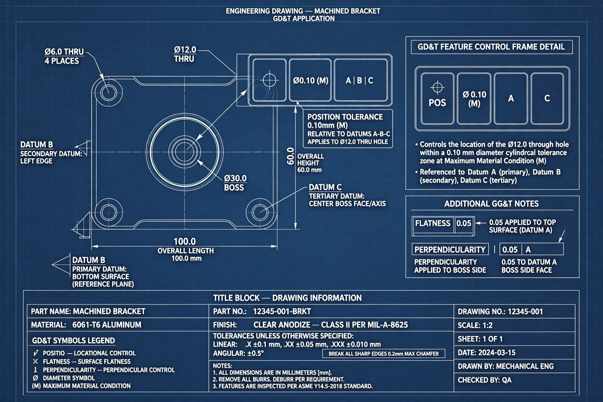
Every GD&T callout lives in a rectangular box called a feature control frame, connected to the feature by a leader line. Read it from left to right, one compartment at a time:
- Geometric symbol: which characteristic is controlled (for example ⌖ for position).
- Tolerance value: the size of the tolerance zone. A diameter symbol (Ø) in front means the zone is cylindrical. Modifiers such as the circled M for MMC follow the value.
- Datum references: the datums the feature is measured from, in order of precedence (primary, secondary, tertiary).
Worked example: a bolt hole pattern
Say a mounting plate has a Ø12.00 mm through hole located by basic dimensions (the boxed dimensions on the drawing) from two edges, and its feature control frame reads: ⌖ | Ø0.10 Ⓜ | A | B | C.
Reading it through: the position symbol says the hole’s location is controlled. The tolerance value says the hole’s axis must stay inside a cylindrical zone 0.10 mm in diameter, positioned at the theoretically exact location (the true position) defined by the basic dimensions. The Ⓜ modifier applies that zone at maximum material condition, when the hole is at its smallest, Ø12.00 mm. If the finished hole measures Ø12.08 mm, it has departed 0.08 mm from MMC, so it earns 0.08 mm of bonus tolerance and the effective zone grows to Ø0.18 mm. Datums A, B and C tell the machinist and the inspector which faces to locate from: the mounting face first, then the two edges. One short frame has specified location, inspection setup and functional fit all at once.
GD&T vs. Traditional Plus-Minus Tolerancing
Plus-minus (coordinate) tolerancing is not wrong; it is simply limited. It locates features with X and Y dimensions from part edges, which creates problems GD&T was designed to solve:
| Aspecto | Plus-minus tolerancing | GD&T |
|---|---|---|
| Tolerance zone for a hole | Square zone from the X and Y tolerances | Cylindrical zone, about 57% more usable area for the same value |
| What it controls | Size and distance from edges | Form, orientation, location and profile relative to functional datums |
| Bonus tolerance | None; the limits are fixed | Available under MMC and LMC, so more good parts pass |
| Inspeção | Setup is open to interpretation; two inspectors can disagree | The datum scheme defines one repeatable setup for everyone |
| Effect on cost | Can scrap functional parts and pass bad ones | Tolerances follow function, reducing rework and disputes |
| Ideal para | Simple parts with generous clearance | Mating parts, hole patterns and precision assemblies |
The classic example is a four-hole bolt pattern. With coordinate tolerances, a hole can sit inside its square zone yet land too far diagonally for the bolt to pass through. GD&T’s round zone follows the bolt circle, so acceptance matches assembly reality. The same idea applies to any location tolerance: a position callout does not just limit how far a hole may drift, it defines the tolerance zone in a way that relates directly to assembly. When you specify a location tolerance, state the basic dimension for each hole from the datums, keep size dimensions (the diameter or width of the feature itself) separate from the basic dimension that locates it, and remember that a single basic dimension is shown boxed on technical drawings to mark it as theoretically exact rather than measured.
When to Use GD&T in CNC Machining
You do not need GD&T on every feature of every part. Use it where function demands it:
- Mating parts and assemblies: position for hole patterns, flatness for faces that bolt together, profile for surfaces that must match a mating contour.
- Sealing surfaces: a flatness callout on a gasket face does more for leak prevention than a tight thickness tolerance.
- Rotating components: runout on shafts and hubs controls vibration and bearing fit in a way size tolerances cannot.
- Thin or flexible parts: profile of a surface captures the whole shape where point-by-point dimensions are impractical.
Skip it, or keep it minimal, on simple brackets, spacers and covers where standard shop tolerances and plus-minus dimensions already guarantee fit. Over-applying GD&T raises inspection time and cost without improving the part. For parts that do need it, Usinagem CNC with clear GD&T callouts quotes faster and inspects more consistently.
For buyers, there is a quoting benefit as well: a drawing with clear datums and position callouts removes ambiguity, so suppliers quote the same part instead of padding prices against the unknown. When you request serviços de usinagem de precisão from XY Machining, complete GD&T on the drawing helps the team program inspection around your datums from the first article onward.

Common GD&T Mistakes to Avoid
- Calling out everything. Applying position, profile and runout to non-critical features makes parts expensive to inspect and slow to quote. Control what affects function.
- Choosing datums that ignore assembly. Datums should be the features the part actually mounts and locates on, not just the easiest faces to reach on the machine.
- Forgetting the basic dimensions. A position frame without boxed basic dimensions leaves the true position undefined and the callout unenforceable.
- Specifying tighter values than the process can hold. A 0.01 mm position tolerance on a large thin plate may be unachievable in production. Match tolerances to capability early, during design review.
- Using concentricity or symmetry out of habit. Both were removed from ASME Y14.5-2018. Position and profile achieve the same functional result and can be verified quickly on a CMM.
- Mixing standards without saying so. ASME Y14.5 and the ISO GPS system differ in defaults (for example, the envelope rule). State which standard governs the drawing in the title block.
GD&T Symbols Reference for Engineers: Applying Geometric Tolerances in Manufacturing
Most engineers keep a GD&T symbols reference close at hand when they define a new drawing, whether that is a printed chart at the workstation or the annotation tools built into modern GD&T tools such as CAD software. Each symbol on the chart represents one geometric characteristic, so a reader can decode a frame without guessing. The core concept is the same in both cases: geometric tolerancing describes what a feature must do, and geometric tolerances put a number on it. In a manufacturing operation, that definition drives everything downstream, from tool selection to dimensional inspection. A well-annotated drawing helps the machinist choose the appropriate cutting tool and inspection method, and helps the inspector’s interpretation of the print match the designer’s intent. Used consistently in any production application, the system can reduce scrap, cut inspection arguments, shorten the path from first article to approved production, and the end user gets parts that assemble correctly the first time.
Conclusão
GD&T is not extra paperwork; it is how a drawing explains what a part must do. Learn the 14 symbols, read feature control frames left to right, and anchor everything to datums, and most production drawings become straightforward. If you are preparing a drawing for manufacture, applying these GD&T and precision machining principles before you send it out will get you cleaner quotes and fewer questions from any shop.
Perguntas frequentes
What are the 14 symbols in GD&T?
The 14 GD&T symbols are straightness, flatness, circularity and cylindricity (form); angularity, perpendicularity and parallelism (orientation); position, concentricity and symmetry (location); profile of a line and profile of a surface (profile); and circular runout and total runout (runout), as defined in ASME Y14.5.
How to read GD&T symbols?
Read the feature control frame from left to right: the first box holds the geometric symbol, the second holds the tolerance value and any modifiers, and the remaining boxes list the datum references in order. Then check the leader line to see which feature the frame controls.
Which GD&T symbols were removed and why?
ASME Y14.5-2018 removed concentricity and symmetry. Both were difficult and expensive to inspect because they required deriving a feature’s exact center from many measurements. Position and profile controls now cover the same functional needs with a simpler, repeatable measurement, so new drawings should use those instead.
What is true position in GD&T?
True position is the exact, theoretically perfect location of a feature, defined by basic dimensions from the datums. The position symbol (⌖) allows the feature’s actual center or axis to move anywhere inside a cylindrical tolerance zone around that true position, which matches how mating parts actually assemble.
When should you use GD&T instead of plus-minus tolerances?
Use GD&T when features must mate, seal, align or rotate together, especially hole patterns and precision assemblies, because it controls function directly and prevents good parts from being scrapped. For simple, non-critical parts with generous clearances, standard plus-minus tolerances are faster to apply and perfectly adequate.