Sheet metal bending is the most common forming operation in metal fabrication. A flat blank is positioned over a die, a punch descends and applies force along a straight axis, and the material deforms into a V, U, or channel profile. It sounds simple, but the engineering behind a clean, dimensionally accurate bend involves material science, tooling geometry, machine capability, and careful design-for-manufacturing (DFM) planning.
This guide covers everything an engineer or product designer needs to know to design sheet metal parts that bend correctly the first time: bending methods, minimum bend radii, K-factor and bend allowance calculations, springback compensation, tolerance expectations, feature placement rules, and common DFM mistakes that drive up cost or cause rejects.
What Is Sheet Metal Bending?
Sheet metal bending is a forming process that deforms a flat metal blank along a straight line to create an angled flange, channel, or enclosure profile. Unlike cutting processes (laser, waterjet, punching) that remove material, bending reshapes the existing blank without material loss. The workpiece is placed on a V-die or channel die, and a matching punch applies downward force until the metal conforms to the desired angle.
During bending, the outer surface of the bend stretches in tension while the inner surface compresses. Between them sits the neutral axis, the imaginary plane where the material neither stretches nor compresses. The position of this neutral axis, expressed as the K-factor, determines how much material is consumed by the bend and is the basis for accurate flat pattern calculations.
Bending is preferred over welding, riveting, or machining for many applications because it produces a continuous, seamless transition between surfaces, adds structural stiffness without adding material weight, and is significantly faster and cheaper than fabricating the same geometry through joined assemblies.
Sheet Metal Bending Methods
Domínio do Ar
Air bending is the most widely used method in modern CNC press brake operations. The punch pushes the workpiece partially into the V-die opening without making full contact with the die bottom. The bend angle is determined by the punch depth, not the die angle, which means a single V-die can produce a range of angles by varying the stroke. Air bending requires the least tonnage (typically 50 to 60% of bottoming), causes minimal tool wear, and allows quick changeovers between different angles. The trade-off is that air bending produces slightly less angular precision than bottoming or coining, with typical tolerances of +/-0.5 degrees to +/-1 degree. Springback is higher in air bending and must be compensated by overbending 2 to 5 degrees depending on material type and thickness.
Bottom Bending (Bottoming)
In bottom bending, the punch forces the workpiece fully against the die surface so the sheet metal conforms closely to the die angle. This requires 3 to 5 times more tonnage than air bending but produces tighter angular tolerances (+/-0.25 to +/-0.5 degrees) and more consistent results across production runs. Springback is reduced because the material is forced further past its yield point. Bottom bending is the preferred method when angular accuracy is critical, such as for enclosures with mating edges or brackets that must align precisely with mounting surfaces.
Cunhagem
Coining applies extreme pressure (5 to 8 times bottoming tonnage) to plastically deform the material fully into the die shape, virtually eliminating springback. The result is the highest angular precision achievable in bending, typically +/-0.1 degrees or better. Coining is used for thin materials (under 1.5 mm) in applications requiring near-zero angular variation, such as small electronic housings and aerospace brackets. The high tonnage requirement causes accelerated die wear, so coining is reserved for precision-critical parts where the cost is justified.
Roll Bending
Roll bending passes the sheet between three adjustable rollers to produce large-radius curves, cylindrical shells, and conical shapes. It is used for ductwork, tanks, pipes, and architectural panels where the bend radius is significantly larger than the material thickness. Roll bending is not suitable for sharp bends or tight radii.
Wipe Bending (Edge Bending)
In wipe bending, the sheet is clamped against a flat pad while a wiping die sweeps the overhanging material downward to form the bend. This method is fast and works well for forming simple flanges and hems, but it requires dedicated tooling for each part profile and is less flexible than air bending for multi-angle work.
Key Engineering Concepts: Bend Radius, K-Factor, Bend Allowance, and Bend Deduction
Raio mínimo de curvatura
The minimum bend radius is the smallest inside radius a material can achieve without cracking on the outer surface. As a general rule, the minimum inside bend radius should be at least equal to the material thickness (1T) for ductile metals like mild steel and aluminum alloys. For harder or less ductile materials like stainless steel 304/316, 7075 aluminum, or spring steel, the minimum radius increases to 1.5T to 3T depending on temper and grain direction. Bending perpendicular to the grain (rolling direction) produces smoother bends with less risk of cracking than bending parallel to the grain. For all XY Machining sheet metal projects, we default to a minimum inside bend radius of 1T unless a tighter radius is specifically called out and verified against material properties.
K-Factor
The K-factor is the ratio of the neutral axis position (measured from the inside surface of the bend) to the total material thickness. It ranges from 0.25 to 0.50, with most sheet metal applications falling between 0.30 and 0.45. A K-factor of 0.33 means the neutral axis sits one-third of the way through the thickness from the inside of the bend. Thinner materials and larger bend radii produce K-factors closer to 0.50 (neutral axis near the center). Tighter bends and thicker materials push the K-factor lower as the neutral axis shifts toward the inside surface. Accurate K-factor values are essential for flat pattern calculations because they determine how much material is consumed by each bend.
Bend Allowance (BA)
Bend allowance is the arc length of the bend measured along the neutral axis. It represents the amount of material that is consumed by the bend itself. The formula is: BA = (pi / 180) x Bend Angle x (Inside Radius + K-Factor x Material Thickness). For a 90-degree bend in 1.5 mm mild steel with an inside radius of 1.5 mm and a K-factor of 0.33, the bend allowance is approximately 3.12 mm. Most CAD software (SolidWorks, Autodesk Inventor, Creo) calculates bend allowance automatically when the correct K-factor and bend radius are entered in the sheet metal environment.
Bend Deduction (BD)
Bend deduction is the amount subtracted from the total of the two flange lengths to arrive at the correct flat pattern length. It equals 2 x (Inside Radius + Material Thickness) minus the Bend Allowance. For the same 90-degree bend example above, the bend deduction is approximately 2.88 mm. In practical terms: measure your two flange lengths from the drawing, subtract the bend deduction for each bend, and the result is the flat blank length that will produce the correct formed dimensions after bending.
Springback: What It Is and How to Compensate
Springback is the elastic recovery of the material after the bending load is released. Every metal springs back partially after bending because the deformation is a combination of plastic (permanent) and elastic (recoverable) strain. The practical effect is that the bend angle opens slightly after the punch retracts, meaning the part ends up at a wider angle than the punch was set to.
Springback magnitude depends on material yield strength, thickness, bend radius, and bending method. High-strength materials (stainless steel, spring steel, high-strength aluminum) spring back more than low-carbon mild steel. Larger bend radii produce more springback than tight radii because a larger proportion of the deformation is elastic. Air bending produces the most springback (typically 2 to 5 degrees for a 90-degree bend in mild steel), while coining produces near zero.
Compensation strategies include overbending (programming the press brake to bend 2 to 5 degrees past the target angle), bottom bending or coining (which physically reduces elastic recovery), and using material-specific springback tables stored in the CNC press brake controller. Modern CNC press brakes with angle-measuring systems can measure the actual bend angle in real time and automatically adjust the stroke to hit the target within +/-0.25 degrees.
Sheet Metal Bending Tolerances: What Is Achievable?
Bending tolerances are governed by material consistency, machine accuracy, tooling condition, and part complexity. Here are the realistic tolerances achievable on modern CNC press brake equipment:
Angular tolerance: +/-0.5 degrees is standard for most commercial sheet metal work. +/-0.25 degrees is achievable with CNC angle measurement and well-controlled material. +/-0.1 degrees requires coining and is limited to thin materials.
Linear tolerance (controlled dimensions): +/-0.1 mm to +/-0.2 mm for backgauge-controlled flange lengths. These are the dimensions directly determined by the backgauge position and are the tightest tolerances a press brake can hold.
Linear tolerance (uncontrolled dimensions): +/-0.3 mm to +/-0.8 mm for dimensions that result from the cumulative effect of multiple bends. Each bend adds approximately +/-0.2 mm of tolerance stack, so a part with four bends accumulates +/-0.8 mm on the final uncontrolled dimension.
ISO 2768-1 reference: For general sheet metal work without specific tolerance callouts, ISO 2768-1 medium (m) class is the default standard. This provides angular tolerances of +/-1 degree for bends up to 10 mm leg length, and +/-0.5 degree for legs over 120 mm. XY Machining holds ISO 2768-m as the baseline for all sheet metal work unless tighter tolerances are specified on the drawing.
DFM Design Rules for Sheet Metal Bending
Following these design rules prevents manufacturing issues, reduces cost, and ensures your parts bend accurately on the first attempt:
Maintain uniform wall thickness. Sheet metal parts are formed from a single-thickness blank. Varying thickness within a part requires secondary machining operations and adds significant cost. Design to a single, standard gauge thickness.
Use a consistent bend radius throughout the part. Changing the bend radius between different bends on the same part requires die changes, which adds setup time and cost. Standardize on one inside radius (typically 1T) for all bends unless a specific radius is functionally required.
Keep bends in the same direction and plane where possible. Each time the part must be flipped or reoriented on the press brake, a new setup is required. Minimizing reorientations reduces labor time and potential for error.
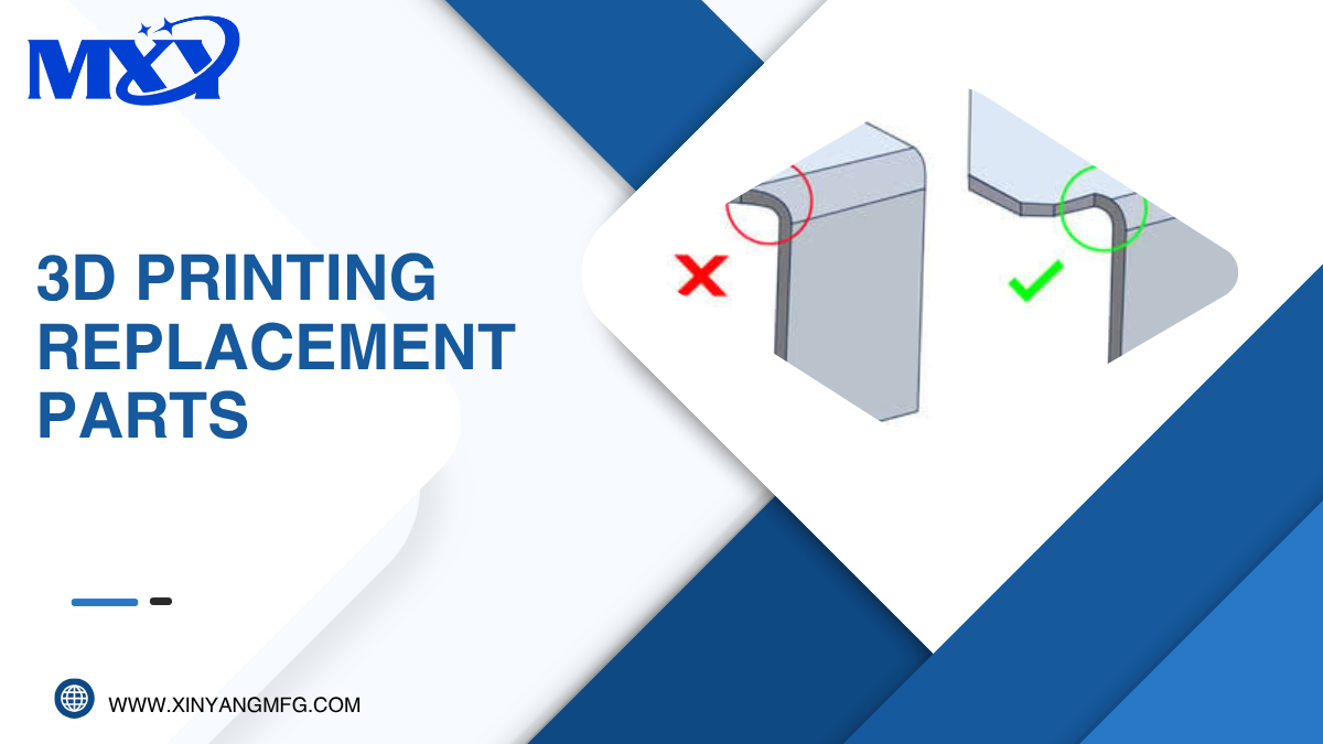
Add bend reliefs at intersecting bends. When a bend line runs into another feature (a perpendicular flange, a slot, or a tab), the material will tear or deform unless a relief cutout is provided. The standard relief width is at least equal to the material thickness, and the relief length should exceed the bend radius. Oblong (rounded) reliefs distribute stress more evenly than rectangular reliefs and are preferred for thinner materials.
Maintain minimum distance between holes/slots and bend lines. Holes, slots, and cutouts placed too close to a bend will distort during forming. The minimum safe distance from the edge of a hole to the nearest bend line is 2T plus the bend radius (2T + R). For slots running parallel to the bend, increase this to 4T.
Minimum flange length. The flange (the material on one side of the bend) must be long enough for the die to engage properly. The minimum flange length is typically 4T or the die opening width divided by 2, whichever is larger. Flanges shorter than this risk slipping off the die or producing inconsistent bend angles.
Bend-to-edge and bend-to-bend spacing. For parts with multiple parallel bends, maintain a minimum distance of 8T between adjacent bend lines to prevent die interference and material buckling. For bends near part edges, keep at least 4T clearance.
Grain direction awareness. Bend perpendicular to the rolling direction (grain) whenever possible, especially for aluminum and stainless steel. Bending parallel to the grain increases the risk of surface cracking on the outer radius. If bends must run in both directions, specify a 45-degree grain orientation as a compromise.
Common Materials for Sheet Metal Bending
Material choice directly affects bend radius, springback, surface finish, and achievable tolerances. Here are the most commonly bent materiais in our shop:
Mild Steel (SPCC, CR, 1018, A36): The most forgiving material for bending. Accepts tight radii (0.8T to 1T minimum), low springback, predictable behavior. Thickness range 0.5 mm to 12 mm.
Stainless Steel (304, 316L, 430): Higher yield strength means more springback (3 to 5 degrees typical for air bending at 90 degrees). Minimum bend radius of 1T to 1.5T. Tends to work-harden, so multiple bends in the same area should be avoided. Excellent corrosion resistance for food, medical, and outdoor applications.
Aluminum (5052, 6061-T6, 5754): 5052 is the most common bending alloy due to excellent formability (0.5T minimum radius). 6061-T6 is significantly harder and more prone to cracking at tight radii (minimum 2T to 3T unless annealed before bending). Springback is moderate. Lightweight and corrosion-resistant.
Copper (C110, C101): Highly ductile with excellent formability. Minimum radius of 0.5T. Low springback. Used for electrical bus bars, RF shielding, and heat sinks.
Brass (C260, C360): Good formability with minimum radius of 0.5T to 1T. Used for decorative parts, electrical connectors, and instrument housings.
Industry Applications of Sheet Metal Bending
Electronics and Telecom: Enclosures, chassis, RF shields, heatsink brackets, rack-mount housings. Tight bend tolerances and clean cosmetic surfaces are typical requirements.
Setor automotivo: Structural brackets, mounting plates, heat shields, battery tray components, and interior trim support frames.
Dispositivos médicos: Instrument housings, cart frames, equipment panels, and stainless steel sanitary covers. Parts often require passivation or electropolishing after forming.
Robótica e Automação: Motor mounts, sensor brackets, cable trays, and enclosure panels for control cabinets. Quick turnaround on design iterations is critical.
Aerospace: Structural brackets, duct sections, avionics enclosures, and ground support equipment. Tight tolerance callouts and full material traceability are standard requirements.
Sheet Metal Bending vs. Alternative Fabrication Methods
Bending vs. Welding: A bent part eliminates the weld joint entirely, which means no heat-affected zone, no filler material, no grinding or finishing of the weld seam, and a stronger cross-section at the transition. Bending is faster, cheaper, and produces a better cosmetic result for any geometry that can be formed from a single flat blank.
Bending vs. CNC Machining: For enclosures, brackets, and panels, bending a flat blank is dramatically cheaper than Usinagem CNC the same geometry from solid billet. Machining removes material (and cost) that bending avoids. However, CNC machining achieves tighter tolerances (+/-0.02 mm) and is the better choice for thick-walled parts or geometries that cannot be formed by bending.
Bending vs. Stamping: Stamping uses dedicated dies to form, blank, and pierce parts in a single press stroke. It is faster than bending at volumes above 10,000 to 50,000 parts but requires $5,000 to $50,000+ in die tooling. For volumes under 5,000, CNC press brake bending with laser-cut blanks is more cost-effective because there is no die investment.
Perguntas frequentes
Qual é o raio mínimo de curvatura para chapas metálicas?
The minimum inside bend radius is generally 1T (equal to the material thickness) for ductile materials like mild steel and 5052 aluminum. For harder materials like 6061-T6 aluminum or stainless steel, the minimum increases to 1.5T to 3T. Bending below the minimum radius causes cracking on the outer surface.
What tolerances can I expect on bent sheet metal parts?
Standard angular tolerance is +/-0.5 degrees to +/-1 degree. Controlled linear dimensions (backgauge-referenced) hold +/-0.1 mm to +/-0.2 mm. Uncontrolled dimensions accumulate approximately +/-0.2 mm per bend. For general work, ISO 2768-m is the default standard.
How do I reduce springback?
Use bottom bending or coining instead of air bending. Specify a tighter bend radius relative to material thickness. Choose a lower-yield-strength material if the application allows. Use a CNC press brake with real-time angle measurement and automatic stroke compensation.
How close can holes be to a bend line?
Maintain a minimum distance of 2T plus the bend radius (2T + R) from the edge of any hole to the bend line. Holes placed closer than this will distort during bending. For slots running parallel to the bend, use 4T minimum clearance.
What is the K-factor and why does it matter?
The K-factor is the ratio of the neutral axis position to the material thickness. It ranges from 0.25 to 0.50 and determines bend allowance, which controls the flat pattern dimensions. An incorrect K-factor produces flat blanks that are too long or too short, resulting in bent parts that do not match the designed dimensions.
Can I bend 6061-T6 aluminum without cracking?
Yes, but with caution. 6061-T6 is a heat-treated alloy with relatively low ductility. Use a minimum bend radius of 2T to 3T, bend perpendicular to the grain direction, and avoid sharp corners. For tighter bends, the material can be annealed (O temper) before bending and re-heat-treated afterward, though this adds cost and lead time.
What is the difference between controlled and uncontrolled dimensions?
A controlled dimension is a flange length that is directly referenced by the press brake backgauge during bending. It holds tight tolerances (+/-0.1 to 0.2 mm). An uncontrolled dimension is any measurement that results from the cumulative effect of multiple bends and cutting operations. Uncontrolled dimensions carry stacked tolerances and should be given wider tolerance bands on the drawing.
What sheet metal thickness range can be bent on a press brake?
Standard CNC press brakes handle 0.5 mm to 12 mm thickness for most materials. Heavier plate (12 mm to 25 mm) can be bent on high-tonnage machines but requires larger die openings and bend radii. At XY Machining, our standard range is 0.5 mm to 12 mm.
How does grain direction affect bending?
Sheet metal has a grain direction from the rolling process. Bending perpendicular to the grain produces smoother bends with lower cracking risk. Bending parallel to the grain increases the chance of surface cracking, especially in aluminum, stainless steel, and high-strength alloys. When bends must run in both directions, specify 45-degree grain orientation.
Does XY Machining offer sheet metal bending services?
Yes. Our fabricação de chapas metálicas services include CNC press brake bending, laser cutting, CNC punching, welding (TIG, MIG, spot), hardware insertion, and surface finishing, all under one roof. We work with aluminum, mild steel, stainless steel, copper, and brass in thicknesses from 0.5 mm to 12 mm.
Conclusão
Sheet metal bending is a fast, cost-effective, and structurally sound forming process, but only when the part is designed with the process in mind. Understanding bend methods, minimum radii, K-factor calculations, springback behavior, and feature placement rules prevents the most common manufacturing issues: cracked bends, out-of-tolerance angles, distorted holes, and parts that do not match the flat pattern.