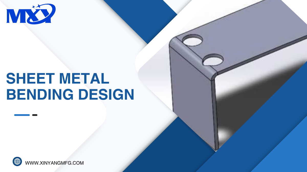
Producing a bent sheet metal part to the correct finished dimensions requires accounting for what the material does during the bend. The outside of the bend stretches; the inside compresses. Somewhere between them lies a plane — the neutral axis — that neither stretches nor compresses. The length of material consumed along the neutral axis through the bend must be added back into the flat-pattern calculation, or every leg on the bent part will be the wrong size.
Three closely related concepts govern this calculation: the K-factor, which describes where the neutral axis sits relative to the material thickness; the bend allowance, which is the arc length consumed along the neutral axis; and the bend deduction, which is the amount subtracted from the outside leg dimensions to arrive at the flat blank length. Get these three values right for a given material, thickness, and bend radius, and the folded part matches the drawing. Get them wrong and every leg is systematically off in the same direction — a repeatable error that can be corrected only if the cause is identified.
This guide provides the governing formulas, practical starting values by material, the design rules that keep bends manufacturable, and an explanation of springback. It is the reference for any engineer designing bent sheet metal parts. For the bending methods that determine how these values are applied in practice — air bending, bottoming, and coining — see our dedicated guide on the three V-bending methods. For the broader range of sheet metal processes, see our sheet metal forming processes guide.
The Neutral Axis and the K-Factor
When a flat sheet is bent, every layer of material parallel to the sheet surface either stretches (on the outside of the bend) or compresses (on the inside). The neutral axis is the theoretical plane within the material thickness at which the strain is zero — neither tensile nor compressive. In a completely unstressed flat sheet, the neutral axis lies at the midplane, which corresponds to a K-factor of 0.5.
As bending occurs, the neutral axis migrates toward the inside surface of the bend. The degree of migration depends on the ratio of the inside bend radius to the material thickness (R/T ratio), the material’s strain-hardening characteristics, and the forming method. Tight radii (low R/T ratio) and harder materials shift the neutral axis further toward the inside surface than large radii in soft materials.
The K-factor quantifies this position as a fraction of the material thickness, measured from the inside face:
K = t / T
where t is the distance from the inside face to the neutral axis and T is the full material thickness.
Typical K-factor values in practice range from 0.30 to 0.50. A K-factor of 0.33 is a widely used starting point for air bending in mild steel. The Machinery’s Handbook and SolidWorks sheet metal references provide K-factor tables for specific material and R/T combinations. For materials run frequently, calibrate the K-factor with a physical test bend: bend a strip at the production radius, measure the actual flat blank consumed, and back-calculate the K-factor from the bend allowance formula.
Bend Allowance Formula
The bend allowance (BA) is the arc length of material consumed along the neutral axis through the bend zone:
BA = theta x (R + K x T)
where theta is the bend angle in radians (degrees x pi/180), R is the inside bend radius, K is the K-factor, and T is the material thickness.
For a 90-degree bend at a 3 mm inside radius in 2 mm thick mild steel with K = 0.33:
theta = 90 x (pi/180) = 1.5708 radians
BA = 1.5708 x (3 + 0.33 x 2) = 1.5708 x 3.66 = 5.75 mm
This means the flat blank must include 5.75 mm of material to form this bend — material that is ‘used up’ in the curve and cannot be counted in either leg length.
Bend Deduction Formula
The bend deduction (BD) is the total amount subtracted from the sum of the outside leg lengths to obtain the flat blank length. It is the complement of bend allowance and is calculated:
BD = 2 x (R + T) x tan(theta/2) – BA
The flat blank length for a simple two-leg part is therefore:
Flat length = Leg A (outside) + Leg B (outside) – BD
Using the same example: BD = 2 x (3 + 2) x tan(45 deg) – 5.75 = 10 x 1.0 – 5.75 = 4.25 mm. If Leg A is 50 mm and Leg B is 40 mm, the flat blank is 50 + 40 – 4.25 = 85.75 mm.
The most common flat-pattern error is mixing inside and outside leg measurement conventions. Bend deduction uses outside leg lengths. If your CAD model reports inside leg lengths, add the material thickness to each leg before applying the bend deduction. Modern CAD systems perform this arithmetic automatically, but they require correct K-factor and inside radius inputs — garbage in, garbage out.
Minimum Bend Radius by Material
Specifying an inside radius below the material’s minimum causes the outer fiber of the bend to crack. The minimum radius depends on the material, temper, and the direction of bending relative to the rolling grain of the sheet.
| Material | Minimum Inside Radius (approx.) | Notes |
| Mild steel (A1011, CR) | 1.0 x thickness | Bend across grain to halve cracking risk |
| Stainless steel 304 | 2.0 x thickness | Work-hardens rapidly; use sharp tooling |
| Aluminium 5052-H32 | 1.5 x thickness | Good general-purpose bending alloy |
| Aluminium 6061-T6 | 3.0 x thickness | Prone to cracking at tight radii; anneal if needed |
| Copper (half-hard) | 1.0 x thickness | Ductile but work-hardens; anneal for severe bends |
| Brass (half-hard) | 1.0 x thickness | Bends well with adequate radius |
These are approximate starting points. The actual minimum radius for a specific alloy lot, thickness, and forming speed should be verified against the material supplier’s data sheet or confirmed with a test bend. Bending across the rolling grain direction (perpendicular to the rolled direction) consistently reduces cracking risk because ductility is higher across the grain. For critical bends in less ductile alloys, specify grain direction on the drawing.
Springback: Causes and Compensation
Springback is the elastic recovery that occurs after the forming force is removed. Every metal deforms both elastically and plastically during bending. The elastic portion recovers when the punch retracts, causing the part to spring back toward its original flat state. The amount of springback is proportional to the material’s yield strength divided by its elastic modulus — the higher this ratio (yield strength / modulus), the more springback.
Practical implications by material:
- Mild steel springback is moderate and predictable — typically 2 to 5 degrees per bend. CNC press brakes compensate with over-bend correction in the program.
- Stainless steel springback is higher — often 5 to 10 degrees — because stainless has a higher yield-to-modulus ratio than mild steel. Close monitoring and per-material correction factors are needed.
- Aluminium 6061-T6 springs back significantly due to its relatively high yield strength. Springback can exceed 8 to 12 degrees for large radii in T6 temper.
- High-strength steels (HSLA, DP steels) require aggressive over-bend compensation; some grades spring back 15 to 20 degrees and can even spring back past 90 degrees unless the bend method is chosen carefully.
Compensation methods include: CNC over-bend correction (adjusting punch depth in the program for the expected springback amount); switching from air bending to bottoming, which reduces springback by conforming the material more fully to the die; and coining, which eliminates most springback by yielding the material fully. For details on when each method is appropriate, see our guide on air bending vs bottoming vs coining.
Practical Design Rules for Bent Sheet Metal Parts
Standardise the inside bend radius across all bends on a part. Using one consistent radius allows a single press-brake tool to form all bends without a tooling change, reducing setup time and cost. Mixing radii on a single part requires multiple tool setups.
Maintain adequate flange length. The minimum flange must be long enough to rest on the die shoulders during the bend. The general rule is a flange length of at least four times the material thickness plus the bend radius. Shorter flanges slip into the die opening and bend at an uncontrolled radius.
Maintain minimum hole-to-bend distance. If a hole is too close to a bend line, the bend operation will deform the hole into an oval. The minimum distance from the edge of a hole to the bend line is typically two material thicknesses plus the bend radius. For holes that must be close to a bend, move the hole to the other leg or add a relief slot.
Add bend relief at the ends of partial bends. When a bend does not run the full width of the part — for example, a tab bent up from the edge of a larger panel — the corners of the bend line are stress concentrations. Without a relief slot or notch, the material will tear at the bend ends. Relief slots should be at least as wide as the material thickness and extend at least one material thickness past the bend line.
Keep flat-pattern dimensions consistent. Specify on the drawing title block whether dimensions are to the inside or outside of bends, and whether flat-pattern or formed dimensions are controlling. Inconsistency in convention is one of the most frequent sources of flat-pattern errors in practice.
Avoid bends parallel to the rolling direction in less ductile alloys. If a bend must be parallel to grain, specify a larger radius or switch to a more ductile temper.
Using CAD for Flat Pattern Development
Modern CAD systems — SolidWorks Sheet Metal, Inventor, Creo, and Fusion 360 — automate flat pattern development once the designer inputs the material, thickness, and K-factor (or bend allowance table). The system calculates bend allowances for each bend and unfolds the part to the flat pattern automatically. This removes the arithmetic burden but does not remove the need to understand the underlying mechanics. If the K-factor is wrong, every flat-pattern dimension will be systematically off. Calibrating K-factor with a physical test bend for each material-thickness-radius combination run in production is essential for tight-tolerance formed parts.
Frequently Asked Questions
What is the K-factor in sheet metal bending?
The K-factor is the position of the neutral axis as a fraction of material thickness, measured from the inside face of the bend. It is 0.5 in a flat, unbent sheet and typically falls between 0.30 and 0.50 during bending, depending on material, thickness, bend radius, and forming method. A value of 0.33 is the common starting point for air bending in mild steel. Calibrate with a physical test bend for materials run regularly.
How do I calculate bend allowance?
Use BA = theta x (R + K x T), where theta is the bend angle in radians, R is the inside bend radius, K is the K-factor, and T is the material thickness. Bend allowance is the arc length of material consumed by the bend zone along the neutral axis. Add it to the flat leg lengths (or subtract the corresponding bend deduction from the outside leg sum) to get the correct flat blank length.
What is the minimum bend radius for sheet metal?
Approximate minimums are: one times material thickness for mild steel and copper; 1.5 times for 5052 aluminium; two times for stainless steel 304; and three times for 6061-T6 aluminium. Always verify against the specific alloy and temper data sheet. Bending across the rolling grain direction reduces cracking risk and allows tighter radii in most alloys.
Why do my bent parts come out the wrong length?
The most common causes are: an incorrect K-factor input in the CAD model; springback not accounted for in the program; tooling wear changing the effective bend radius; or inconsistent conventions between inside and outside leg measurements. Calibrate the K-factor with a test bend at the production radius and material, verify that the CNC program includes springback correction, and confirm that dimension conventions are consistent throughout the drawing.