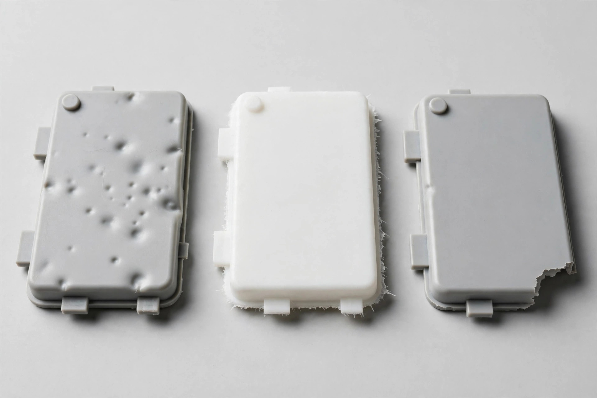
Most injection molding defects come from four sources: part design, the mold, the process settings, or the material. Sink marks, warpage, short shots, flash, burn marks and weld lines are the ones buyers see most, and each has a short list of likely causes.
Quick answer: Sink marks and warpage usually trace back to uneven or thick walls. Short shots and burn marks point to flow and venting. Flash points to clamping, worn parting lines or too much pressure. Weld lines and jetting depend on gate location. Fix design problems in CAD, tool problems in steel, and process problems on the press.
Quick Reference: Defects, Causes and First Fixes
Below is a quick reference to the main molding defects, then each one in more detail.
| Defect | What you see | Likely causes | First fixes to try |
|---|---|---|---|
| Sink marks | Shallow dents over thick areas | Thick walls, ribs or bosses; low packing | Core out thick sections; raise pack and hold |
| Warpage | Part bends or twists after ejection | Uneven walls or cooling; resin shrinkage | Even out walls; balance mold cooling |
| Short shot | Part not fully filled | Low pressure or speed; trapped air; thin flow path | Add vents; raise injection pressure or temperature |
| Flash | Thin fins at parting line or pins | Low clamp force; worn tool; high pressure | Repair shutoffs; adjust pressure and clamp |
| Burn marks | Black or brown streaks at end of fill | Air compressed and heated (dieseling) | Improve venting; slow injection |
| Flow lines | Wavy lines or rings | Melt cooling as it fills | Raise melt and mold temperature; speed up fill |
| Weld lines | Visible line where flows meet | Flow fronts meet too cool | Move gate; raise temperature; vent the meeting point |
| Jetting | Snake-like pattern near gate | Melt shoots into open cavity | Change gate position or size; slow initial fill |
| Voids | Bubbles inside thick sections | Shrinkage in thick areas; moisture | Thin the section; dry the resin; raise packing |
| Splay | Silver streaks on surface | Moisture or degraded resin | Dry material properly; check melt temperature |
Sink Marks and Voids
Sink marks form when a thick section keeps shrinking after its surface has frozen. The surface is pulled inward and leaves a dent. Voids are the internal version: the skin holds, so the shrinkage opens a bubble inside.
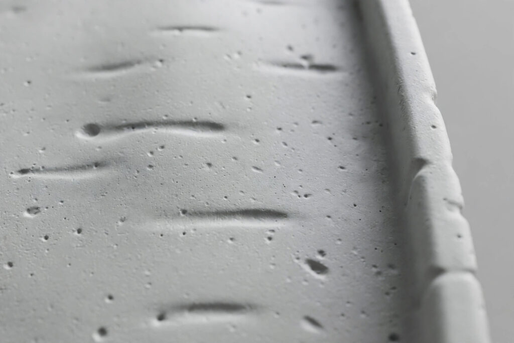
The best fix is in the design. Keep walls as uniform as possible and core out thick areas. Published design guidance from molders commonly puts ribs and thin walls at roughly 40 to 60 percent of the adjoining wall thickness to limit sink. Process changes such as longer hold time help, but they cannot fully rescue a part with heavy sections.
Warpage
Warpage happens when different areas of a part shrink by different amounts. Thick and thin sections cool at different rates, and so do the two halves of a mold if cooling is unbalanced. Semi-crystalline resins such as nylon and polypropylene shrink more than amorphous resins such as ABS and polycarbonate, so they warp more readily.
Uniform walls, balanced cooling channels and ribs that stiffen long flat areas are the main tools. Shrinkage behavior is measured under ASTM D955, and a resin datasheet showing different flow and cross-flow shrink is an early warning sign.
Short Shots, Burn Marks and Flash
These three molded part defects often share a cause: how air and melt move through the cavity.
Short shots
Short shots occur when plastic freezes or gets blocked by trapped air before the cavity fills. Thin walls far from the gate, low pressure or speed, and poor venting are the usual reasons.
Burn marks
Burn marks are trapped air that gets compressed and heated until it scorches the resin, often called dieseling. They appear at the last place to fill. Better venting usually solves them faster than any setting change.
Flash
Flash is the opposite problem: plastic escapes where it should not, at the parting line, around ejector pins or at slides. Worn or damaged shutoffs, low clamp force and excessive injection pressure all cause it. On an older tool, flash often means the steel needs repair, not new settings.
Flow Lines, Weld Lines and Jetting
These molding defects are mostly cosmetic, but on visible surfaces they cause the most rejections.
Flow lines
Flow lines are wavy patterns where melt slowed and began to cool as it filled. Higher melt and mold temperature and faster injection help.
Weld lines
Weld lines, also called knit lines, form where two flow fronts meet around a hole or core. They are a cosmetic issue and a weak point. Gate placement decides where they fall, so move them away from cosmetic faces and load paths. Gate style and position affect how the melt fills the cavity, so agree on them during DFM.
Jetting
Jetting happens when melt shoots across an open cavity instead of flowing smoothly against a wall. Gating into a wall or pin, or slowing the start of injection, usually stops it.
Material Defects: Splay, Discoloration and Delamination
Hygroscopic resins such as polycarbonate and nylon absorb moisture from the air. If they are not dried before molding, the water turns to steam and leaves silver streaks called splay. Degraded resin from excessive temperature or long residence time causes discoloration and black specks. Contamination or incompatible colorants can cause surface layers to peel, known as delamination.
These molding problems are fixed at the material handling stage: correct drying, clean hoppers and appropriate regrind ratios. Material choice also matters. Our thermoplastic vs thermoset guide compares the two resin families and their processing differences.
| Defect | What you see | Likely cause | First fix |
|---|---|---|---|
| Splay | Silver streaks on the surface | Moisture in hygroscopic resin | Dry the material properly |
| Discoloration | Discoloration and black specks | Degraded resin from excessive temperature or long residence time | Check melt temperature and residence time |
| Delamination | Surface layers peel | Contamination or incompatible colorants | Check material and colorant compatibility |
How to Diagnose Molding Defects on a New Tool
When first samples come back with defects in molded parts, work through them in order instead of changing several settings at once.
| Step | What to check | What it tells you |
|---|---|---|
| Run a short-shot study | Mold a series of deliberately incomplete parts | The last areas to fill predict where burn marks, short shots and weld lines will appear |
| Check the material record | Drying time and temperature, regrind percentage, resin lot | Splay and discoloration often stop here |
| Change one variable at a time | Change one setting and record each change | The fix can be repeated on the next run |
| Compare with mold flow simulation | Compare defects with the simulation run during DFM | A defect the simulation predicted usually needs a design or tool change, not a new setting |
Simulation results are only as good as the material data behind them, so treat them as a guide to likely molding problems, not a guarantee.
Who Owns the Fix for Injection Molding Defects?
Most delays happen because nobody is sure who should fix an injection molding defect. Sorting defects by root cause makes that clear:
| Root cause | Typical defects | Who fixes it |
|---|---|---|
| Part design | Sink, voids, warpage, weld lines in bad places | Product designer, with DFM input |
| Tooling | Flash, burn marks, short shots from poor venting, jetting | Toolmaker |
| Process | Flow lines, short shots, sink from low packing | Molder on the press |
| Material | Splay, discoloration, delamination | Molder and resin supplier |
This view also prevents a common mistake: trying to tune a design problem out with process settings. A narrow process window might pass first samples and then drift in production.
We would rather change the CAD or the steel once than fight the same defect every run. Good mold and tool making starts with that DFM conversation, and gate and runner choices, including hot runner versus cold runner systems, affect several defects in the table.
Writing Defect Limits Into Your RFQ
Many disputes over molding defects come from drawings that never say what is acceptable. Before tooling starts, agree on:
- Cosmetic zones. Mark which faces are visible and which are hidden, and state what is allowed on each.
- Gate, ejector and parting line locations. Approve them on the DFM report so marks land on hidden faces.
- Tolerances. Reference a standard such as ISO 20457, which defines tolerance groups for molded plastic parts, instead of applying machining tolerances.
- Limit samples. Keep signed examples of the worst acceptable weld line or flow mark after first samples.
Inspection records for first articles are part of our quality assurance process.
Frequently Asked Questions
What are the most common defects in injection molding?
The most common are sink marks, warpage, short shots, flash, burn marks, flow lines, weld lines and jetting. Material problems such as splay and discoloration are also frequent. Most trace back to wall thickness, gate and vent design, process settings or poorly dried resin, so each defect has a short list of likely causes.
What are the typical tolerances for injection molds?
Molded part tolerances depend on resin, part size, wall thickness and tool quality, so there is no single number. Standards such as ISO 20457 define tolerance groups for molded plastic parts. Mold steel itself is machined much tighter than the parts it makes, because resin shrinkage adds its own variation.
What is the average lifespan of a plastic injection mold?
Lifespan depends on steel, resin and maintenance. The industry classification from the Plastics Industry Association runs from Class 101 molds, built for a million or more cycles, down to Class 105 prototype tools for very small quantities. Aluminum tools suit lower volumes, while hardened steel tools last longest.
How can you tell if something has been injection molded?
Look for a small gate mark where plastic entered, round ejector pin marks on hidden faces, and a thin parting line where the mold halves met. Molded parts also have draft on vertical walls and uniform walls with ribs. These features are hard to avoid, which is why designers plan where they appear.
What causes sink marks in injection molding?
Sink marks are caused by thick sections that keep shrinking after the surface freezes. Ribs, bosses and wall junctions that are too thick are the usual source. Thinner, uniform walls are the main fix, supported by enough packing pressure and hold time, and by placing the gate closer to thick areas.
Preventing Injection Molding Defects Before the Tool Is Cut
The cheapest defect is one designed out before steel is cut. Uniform walls, sensible draft of at least half a degree (more on textured faces), planned gate and vent locations, properly dried resin and agreed cosmetic limits prevent most of the molding defects covered in this guide.
Every resin and tool behaves a little differently, so treat the fixes above as starting points to confirm with your molder. If you are planning a new part, send it to XY Machining for a DFM review, or see how our injection molding services run from first samples to production.