What are the best 3D printing infill patterns for strong and efficient prints? How does 3D printing infill density affect part strength, weight, material usage, and printing time? Which 3D print infill settings should you choose for prototypes, functional parts, or production components?
The right 3D printing infill pattern depends on the purpose of your part. For lightweight models, grid or gyroid patterns with lower density can reduce material use, while functional components often require stronger patterns such as cubic, honeycomb, or gyroid with higher density. Infill density, pattern direction, and slicer settings directly influence mechanical performance, print duration, and overall cost.
3D printing is widely used for prototyping, engineering validation, and low-volume manufacturing because it allows manufacturers to create complex parts quickly without expensive tooling. However, the internal structure of a printed part plays a major role in its final performance. Choosing suitable 3D printing infill patterns helps achieve the correct balance between strength, weight, flexibility, and production efficiency.
For businesses requiring professional additive manufacturing solutions, 3D printing services can provide engineering-grade parts using advanced printing technologies and suitable material selection.
What Is 3D Printing Infill?
Infill refers to the internal structure printed inside a 3D model. Instead of creating a completely solid object, most 3D printers create an outer shell and fill the inside with a controlled pattern. This approach reduces material consumption while maintaining enough strength for the intended application.
A fully solid print may provide maximum strength, but it increases material cost, printing time, and weight. Infill allows engineers and designers to customize the internal structure according to performance requirements.
The main factors that control infill performance include:
| Facteur | Impact on 3D Printed Part |
| Infill Density | Determines internal material amount and overall strength |
| Infill Pattern | Controls load distribution and mechanical behavior |
| Épaisseur de la paroi | Improves external strength and surface durability |
| Print Orientation | Changes how forces affect the final part |
Understanding these factors is important when preparing designs for professional manufacturing workflows, including rapid prototyping services.
How Does 3D Printing Infill Density Affect Performance?
3D printing infill density represents the percentage of internal material inside a printed object. A 10% infill means the model contains approximately 10% internal structure, while a 100% infill creates a completely solid part.
Low-density infill is useful for decorative models, visual prototypes, and lightweight components. Higher-density infill is preferred for parts that experience mechanical stress, impact, or repeated use.
The correct density depends on the application:
| Application | Recommended Infill Density | Common Patterns |
| Decorative models | 5–15% | Lines, Grid |
| General prototypes | 15–30% | Grid, Gyroid |
| Functional components | 30–60% | Cubic, Honeycomb, Gyroid |
| High-strength parts | 60–100% | Cubic, Solid Fill |
Increasing density does improve strength, but it also increases printing time and material consumption. In many cases, improving wall thickness and selecting the right pattern can provide better results than simply increasing infill percentage.
Common Types of 3D Printing Infill Patterns
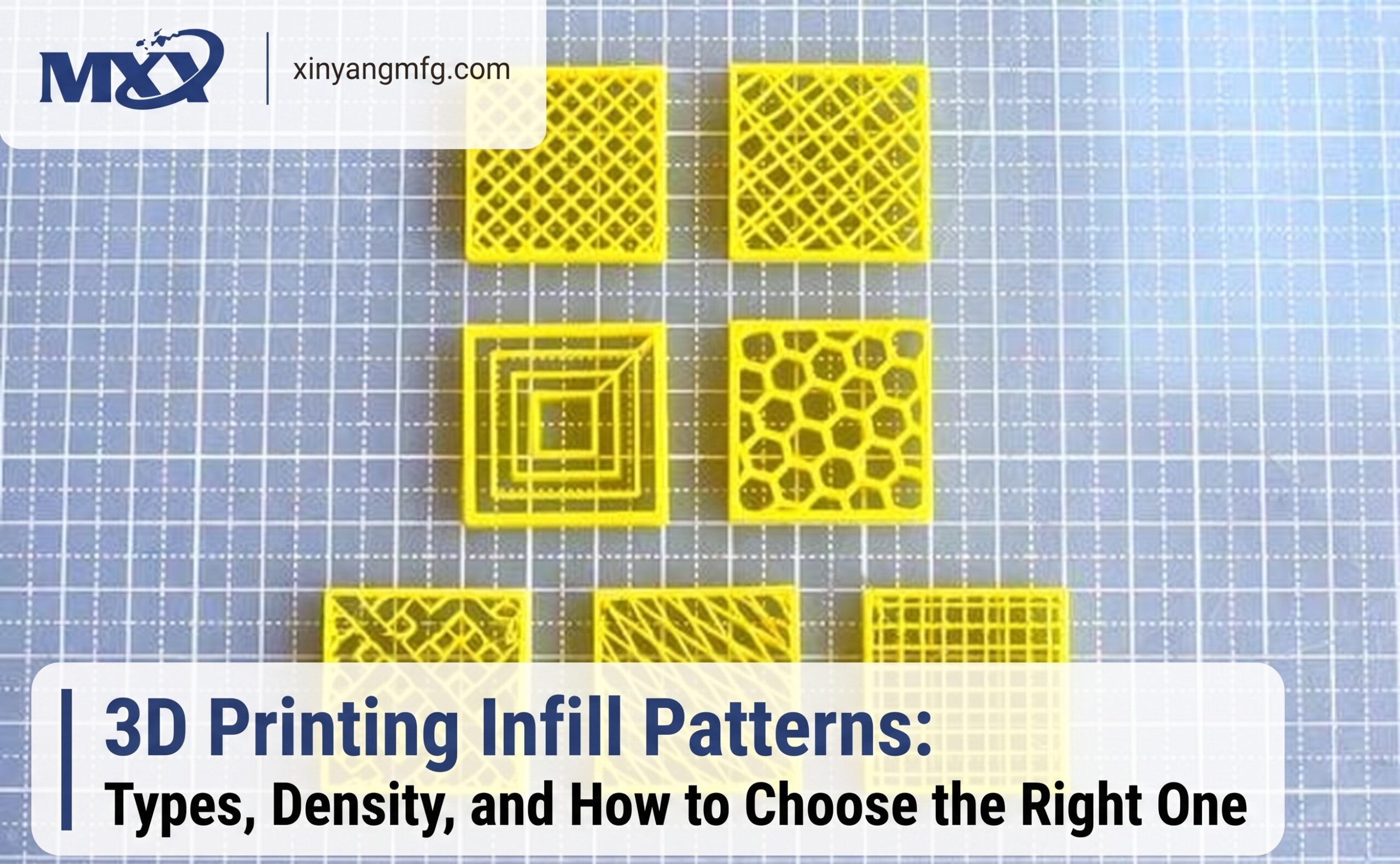
Different infill patterns are created to handle different performance requirements. Each pattern distributes forces differently, which affects durability and flexibility.
Grid Infill Pattern
The grid pattern is one of the most commonly used options in desktop and industrial 3D printing. It creates a simple cross-linked structure that provides balanced strength in multiple directions.
Grid infill is suitable for everyday prototypes, visual models, and parts that need moderate durability. It offers a good combination of printing speed and mechanical support.
Honeycomb Infill Pattern
Honeycomb structures are inspired by natural designs that provide excellent strength while maintaining low weight. The hexagonal structure distributes forces efficiently and is widely used for lightweight engineering applications.
This pattern is useful when a part requires strength without adding excessive material weight.
Gyroid Infill Pattern
Gyroid is a three-dimensional continuous structure that provides excellent strength distribution. Unlike some traditional patterns, it creates smooth internal curves that can handle forces from different directions.
Many engineers prefer gyroid for functional prototypes because it provides a strong balance between durability, flexibility, and material efficiency.
Cubic Infill Pattern
Cubic infill creates a three-dimensional cube-based structure. It offers strong performance because the internal geometry supports loads from multiple angles.
This pattern is commonly selected for mechanical parts, brackets, fixtures, and components exposed to regular stress.
Lines Infill Pattern
Lines infill is simple and fast to print. It creates parallel internal lines that support the upper layers of the model.
It works well for simple prototypes and parts where speed is more important than maximum strength.
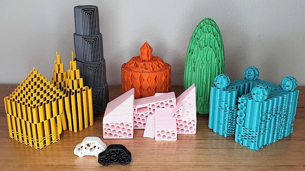
How to Choose the Best Infill Pattern for 3D Printing?
Choosing the best infill pattern for 3D printing depends on several factors, including the purpose of the part, expected forces, material type, and production requirements.
For example, a prototype used only for visual approval does not require the same internal structure as a mechanical component used in an industrial environment.
Consider these questions before selecting an infill pattern:
- Will the part experience impact or pressure?
- Does the component need flexibility or rigidity?
- Is reducing weight important?
- Is printing speed more important than maximum strength?
- Will the part be used for testing or final application?
For engineering projects, combining proper infill selection with suitable materials and manufacturing methods creates better results. Companies often evaluate these factors during the design for manufacturing process before production begins.
Important 3D Print Infill Settings
Besides pattern and density, slicer settings influence the final quality of a printed part. Important settings include:
Hauteur de couche
Lower layer heights improve surface quality and detail but increase printing time. Larger layer heights are useful for faster prototypes.
Épaisseur de la paroi
Walls contribute significantly to strength. Increasing wall count can sometimes improve durability more efficiently than increasing infill density.
Printing Temperature
Material temperature affects layer bonding. Correct temperature settings improve adhesion between printed layers.
Print Orientation
The direction of printing changes how forces travel through the part. Proper orientation can improve strength without increasing material usage.
Recommended Infill Choices for Different Applications
| Project Type | Suitable Infill Choice | Raison |
| Concept models | Lines or Grid | Faster printing with lower material usage |
| Product prototypes | Gyroid or Cubic | Better balance of strength and efficiency |
| Functional parts | Honeycomb, Cubic, Gyroid | Improved mechanical performance |
| Lightweight components | Gyroid | Strength with reduced weight |
| Stress-bearing parts | Higher density Cubic | Better load handling |
How Manufacturers Use Infill Optimization
Professional manufacturers analyze part requirements before selecting printing parameters. A prototype for testing airflow, product shape, or assembly fit may require different settings compared with a final-use component.
Industrial additive manufacturing combines material selection, machine capability, print orientation, and internal structure optimization. This approach helps reduce failures and improves consistency across multiple parts.
For companies moving from prototypes to production, combining 3D printing with other manufacturing methods such as Services d'usinage CNC can provide a complete product development workflow.
Conclusion
Selecting the correct 3D printing infill patterns is an important step in creating efficient and reliable printed parts. Infill density, pattern design, and print settings work together to determine strength, weight, cost, and production speed.
There is no single infill pattern that works for every project. The best choice depends on whether the goal is a quick prototype, lightweight design, functional testing, or a production-ready component.
By understanding different patterns such as gyroid, cubic, honeycomb, grid, and lines, designers can create parts that match real performance requirements while avoiding unnecessary material use.
For professional manufacturing projects, working with experienced engineers helps ensure the right combination of technology, materials, and print settings for successful results.
Foire aux questions
What is the strongest 3D printing infill pattern?
Gyroid and cubic patterns are considered among the strongest options because they distribute forces through three-dimensional structures. The final strength also depends on material, wall thickness, print direction, and density.
What is the ideal 3D printing infill density?
For most general-purpose prints, 15% to 30% density provides a good balance between strength and material usage. Functional parts often require higher density based on their operating conditions.
Does higher infill density always make a stronger print?
Higher density usually increases strength, but it also increases weight and printing time. A better pattern, thicker walls, and correct print orientation may improve performance more efficiently.
Which infill pattern is best for functional parts?
Gyroid, cubic, and honeycomb patterns are commonly selected for functional parts. The final choice depends on the type of load, material, and expected environment.
Can infill settings reduce 3D printing costs?
Yes. Selecting suitable infill density and pattern can reduce material consumption and shorten production time. Proper optimization avoids unnecessary internal material while maintaining required performance.
À propos de l'auteur Patrick Chen — Ingénieur d'application, XY Machining Patrick examine les conceptions à parois minces pour les équipes d'ingénierie américaines chez XY Machining et collabore avec l'atelier sur les dispositifs de serrage et les parcours d'outils qui permettent de maintenir les pièces délicates dans les tolérances. Pour tester la résistance à la pression d'une pièce à parois minces avant d'établir un devis, Envoyez votre modèle à notre équipe.