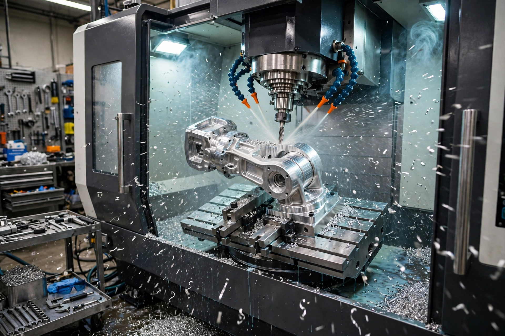
Mecanizado CNC for robotics is the process of using computer-controlled cutting machines to make precision robotic components from engineering metals and plastics, from a single prototype through full production runs. In 2026, with the global robotics market adding about 500,000 new industrial robot installations a year (IFR, 2025), demand for precision-machined robotic parts has never been higher.
This guide covers how CNC machining for robotics works across prototypes and production: speed and iteration, tolerances, materials, surface finishes, inspection, and costs. If you are comparing processes, start with our guide to CNC machining for robotic automation.
Why CNC Machining for Robotics Works for Prototypes and Production
The key advantage over alternative manufacturing methods is that the same material, same tolerances, and same inspection processes apply at the prototype stage. Data gathered during prototype testing therefore predicts production behavior accurately, avoiding the costly “it worked in prototyping but failed in production” failure mode.
The same machine, tooling approach, and material work identically for prototyping and production. That overlap is what makes CNC machining uniquely valuable for robotic development, where a design may pass through 4 to 8 revision cycles before freeze. For early geometry checks, 3D printing can still be faster — see our comparison of Impresión 3D frente al mecanizado CNC.
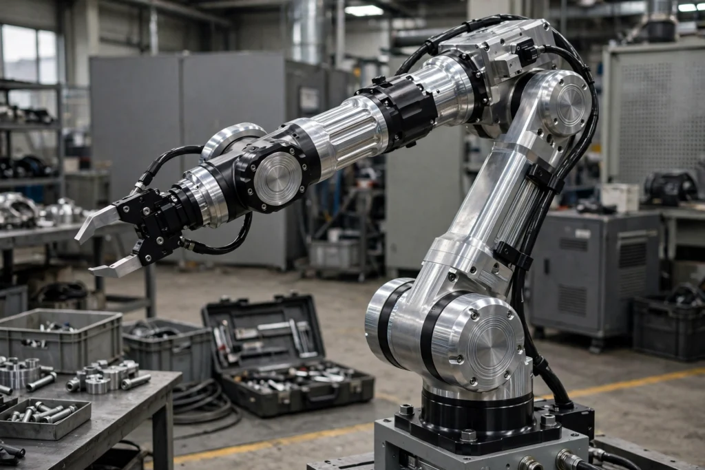
CNC Machining for Robotic Prototypes: Speed and Iteration
Robotic prototype machining runs on a specific tempo: fast turnaround, frequent revisions, and low quantity per revision cycle. Engineering teams typically run 4 to 8 design cycles on key robotic components before design freeze, with 2 to 10 parts per cycle.
The fastest turnaround for aluminum robotic prototypes is 3 to 5 business days for relatively simple single-setup parts, such as a motor mount or structural bracket in aluminum 6061. Moderate-complexity parts — multi-setup housings with precision bores and compound angles — run 7 to 10 days, and complex assemblies needing 5-axis machining and finishing add another 3 to 5 days. For the step after prototyping, see Prototipado rápido frente a fabricación rápida de utillaje frente a utillaje de producción.
| Fase | Material común | Motivo |
|---|---|---|
| Prototipo conceptual | Aluminio 6061-T6 | Rápido, barato y las máquinas limpian bien |
| Validación técnica | Aluminio 6061 o 7075 (destinado a la producción) | Se ajusta a las propiedades del material de producción |
| Producción | Aluminio 7075-T651 o 6061-T6 (especificación «frozen») | Coherente, trazable, certificado |
CNC Machining for Robotic Production Parts: Consistency at Scale
Production CNC machining for robotic components runs on different success metrics than prototyping. The question changes from “did the prototype work?” to “can we make 500 of these identically, on schedule, with documentation?” Consistency is the paramount production quality metric.
Every unit in a production run of 500 joint housings must be identical within drawing tolerance, with material certification on file and inspection data recorded. At 500 units a month, 100% CMM inspection of every feature would cost more than the machining itself, so production uses statistical process control with sample inspection — and full checks on critical features. Our Tolerancias en el mecanizado CNC guide explains the tolerance bands production parts are held to.
Requisitos de tolerancia para los distintos tipos de componentes robóticos
Bearing seats, pilot diameters, and bore concentricity carry the tightest tolerances on a robot; wall thickness, pocket depth, and cover geometry accept standard tolerances. The table below shows typical values — always confirm the final numbers on your drawing, and use GD&T symbols to call out datums and feature control frames.
| Componente | Características fundamentales | Tolerancia estrecha | Características de serie | Tolerancia estándar |
|---|---|---|---|---|
| Caja de juntas | Asiento del diámetro exterior del rodamiento | ±0,012 mm (H7) | Espesor de la pared, profundidad de la cavidad | ±0,1 mm |
| Soporte para servomotor | Diámetro del piloto | ±0,01 mm | Distribución de los orificios de los tornillos | ±0,05 mm |
| Enlace estructural del brazo | Interfaz de perno plana | ±0,02 mm | Aligerar los bolsillos | ±0,2 mm |
| Carcasa del accionamiento armónico | Concentricidad del orificio | <0,005 mm TIR | Superficies exteriores | ±0,1 mm |
| Cuerpo del efector final | Funciones de registro parcial | ±0,01 mm | Geometría de la cubierta | ±0,1 mm |
| Caja de engranajes | Distancia entre centros de los orificios | ±0,02 mm | Características de las paredes | ±0,15 mm |
A prototype bearing housing needs dimensional accuracy on the bearing seats (±0.012 mm), but non-critical surfaces can accept wider tolerances, and material certification documentation is not needed for design validation. Production parts reverse that: every unit must match, with certification and recorded inspection data.
Materials for CNC-Machined Robotic Parts
Aluminum dominates robotic prototyping and production: 6061-T6 for concept prototypes and engineering validation, 7075-T651 or 6061-T6 for frozen production specs. The mistake to avoid is validating in 6061 to save cost, then switching to 7075 in production without re-testing — 7075 has roughly 40% higher yield strength than 6061, but it is more notch-sensitive and behaves differently under fatigue loading.
If the structural validation was done on 6061, the 7075 production part has not been validated. Compare the two alloys in our 6061 vs 7075 aluminum CNC machining guide, and see Mecanizado CNC del titanio frente al del aluminio when weight and strength push beyond aluminum.
Surface Finishes and Anodizing for Robotic Parts
Surface finish must conform to the production specification, and finishes change dimensions — plan for them on the drawing, not after machining. Hardcoat Anodize Type III builds about 0.001″ to 0.002″ per face, so a bore with hardcoat on both sides ends up 0.002″ to 0.004″ smaller in diameter.
Bearing seat bores that must end up at H7 fit after anodizing have to be machined oversize to allow for the buildup — a common source of first-article rejections. See anodizing Type II vs Type III for the two anodize types, and our CNC machining surface finish guide for the full finish range.
Inspection and Quality: FAI, CMM, and Documentation
Standard production robotic CNC parts should ship with a dimensional inspection report showing actual measurements against drawing tolerances for all critical features, a material certificate of conformance for alloy grade and heat treatment, and a surface finish certificate where a finish is called out. First article inspection packages should measure every drawing characteristic.
Run a formal first article inspection (FAI) on the first production unit — for robotic manufacturing systems going to end customers, a documented FAI that measures every drawing characteristic and records actual results confirms the process can meet the specification. Our first article inspection guide for CNC machining explains what an FAI package contains.
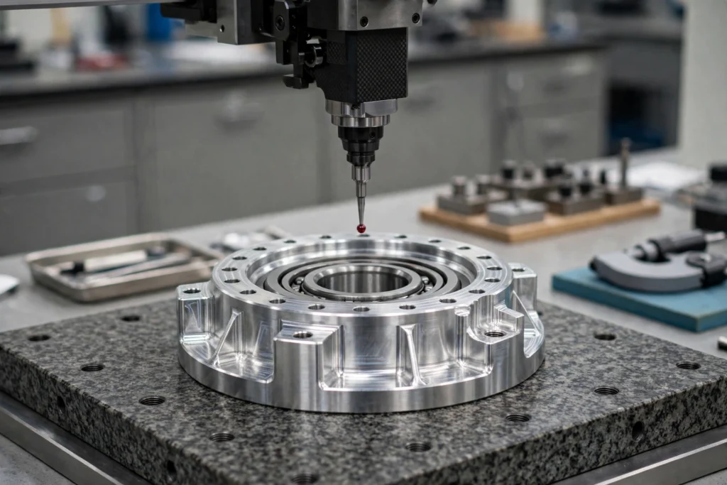
Gestión de la transición del prototipo a la producción
Freeze the design before transitioning suppliers — re-qualifying a new supplier on a design that is still changing wastes engineering and supplier resources. The prototype that qualifies the design for production should be made by the production supplier, on the production machines, with the production inspection plan.
Use production-intent processes for late-stage validation prototypes, and document the inspection plan before production starts: which features need 100% inspection, which are statistically sampled, and at what frequency. See bridge tooling vs production tooling for the tooling step between prototype and production volumes.
How Much Does CNC Machining for Robotics Cost
CNC machining is economical for robotic components from 1 piece through about 5,000 to 10,000 pieces per year, depending on complexity. Below about 200 pieces per year, the per-unit cost is hard to beat because there is no tooling investment; above 5,000 to 10,000 pieces a year, die casting or precision investment casting can become cost-competitive for simple geometries.
The cost drivers are material, complexity, tolerance, finish, and quantity — tight-tolerance bores and 5-axis work cost more than simple 2.5D brackets. Our Coste del mecanizado CNC guide breaks down how each factor moves the price.
Frequently Asked Questions About CNC Machining for Robotics
¿Cuál es la diferencia entre un prototipo robótico y una pieza de producción desde el punto de vista del mecanizado CNC?
Prototypes and production parts use the same CNC process and the same material. The difference is quantity (1 to 10 for prototypes vs. 50 to thousands for production), inspection rigor (100% inspection with reports for production vs. dimensional spot-check for prototypes), material documentation (mill certs required for production, optional for prototypes), and process stability (production requires documented SPC; prototypes do not).
¿Cuántas iteraciones de prototipos debería prever para los componentes robóticos CNC antes de dar por definitivo el diseño?
Most robotic joint housing and structural component designs go through 3 to 6 iterations before design freeze. Simple brackets may stabilize in 1 to 2 cycles, while complex multi-joint housings with motion accuracy requirements commonly take 4 to 8 cycles as tolerance refinements, geometry optimizations, and assembly learnings accumulate. Budget for at least 4 prototype cycles even if you expect fewer.
¿Debería utilizar la impresión 3D o el mecanizado CNC para los prototipos robóticos?
Use 3D printing for early geometry and concept validation where dimensional accuracy is not yet critical. Transition to CNC machining as soon as you are validating bearing fits, motor alignment, structural stiffness, or any feature where the final design will be CNC machined in production — testing a 3D printed robotic joint does not tell you how the CNC machined production joint will behave. See Impresión 3D frente al mecanizado CNC for the full comparison.
¿Cómo afecta el anodizado a las tolerancias dimensionales de las piezas fabricadas con máquinas CNC robotizadas?
Hardcoat Anodize Type III builds approximately 0.001″ to 0.002″ per face. On a bore diameter, hardcoat on both sides reduces the bore by 0.002″ to 0.004″ total. Bearing seat bores that need to end up at H7 fit tolerance after anodizing must be machined oversize to account for the anodize buildup — a common source of first-article rejections when the anodize allowance is not factored into the machining drawing.
¿A partir de qué volúmenes de producción resulta rentable el mecanizado CNC para los componentes robóticos?
CNC machining is economical for robotic components from 1 piece through approximately 5,000 to 10,000 pieces per year depending on complexity. Below approximately 200 pieces per year, the per-unit cost of CNC machining is unbeatable because there is no tooling investment. Above 5,000 to 10,000 pieces annually, die casting or precision investment casting may become cost-competitive for simple geometries.
Need CNC-machined parts for a robotic prototype or production run? Send your drawing for a quote — ponte en contacto con nosotros and we will confirm material, tolerance, and lead time.